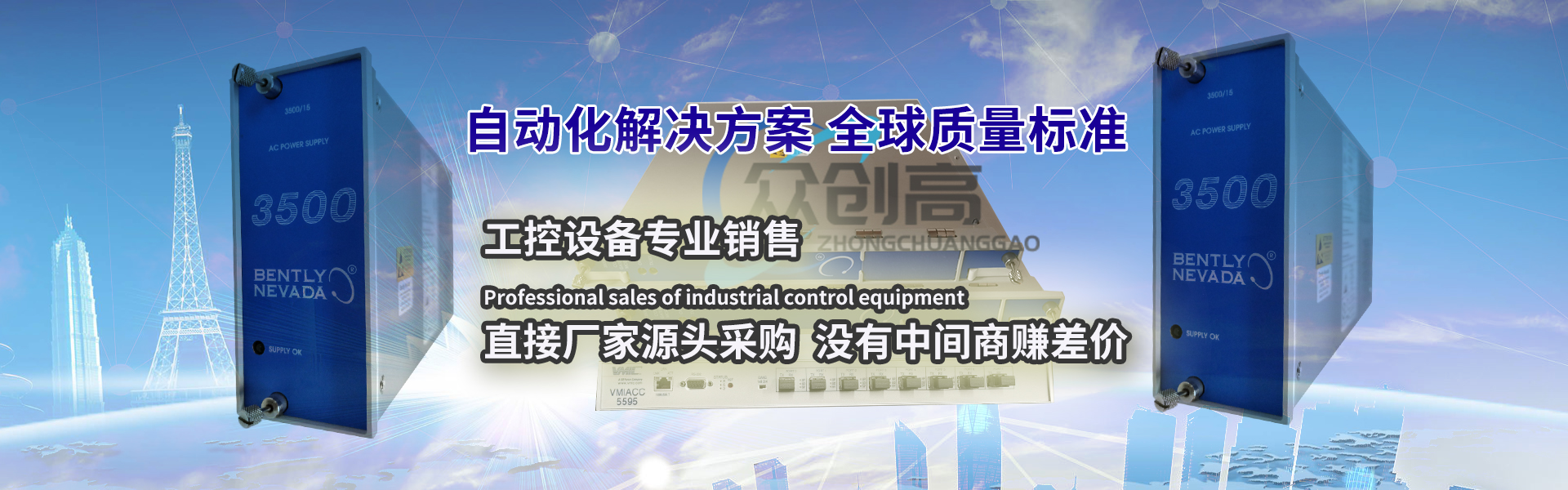

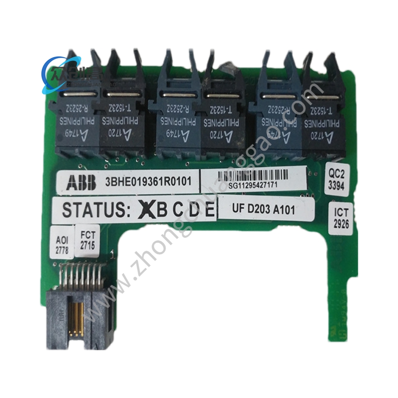
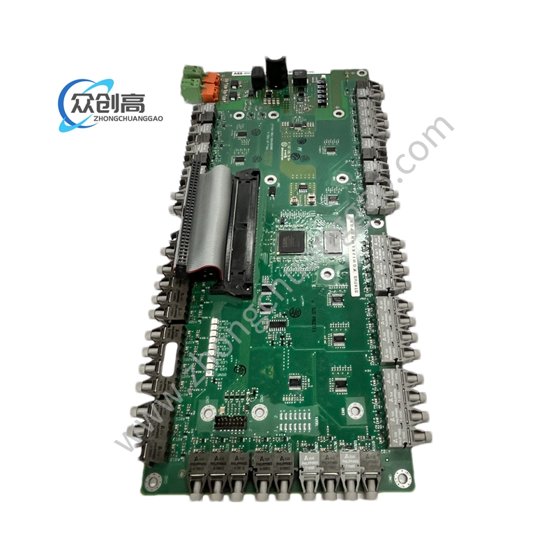
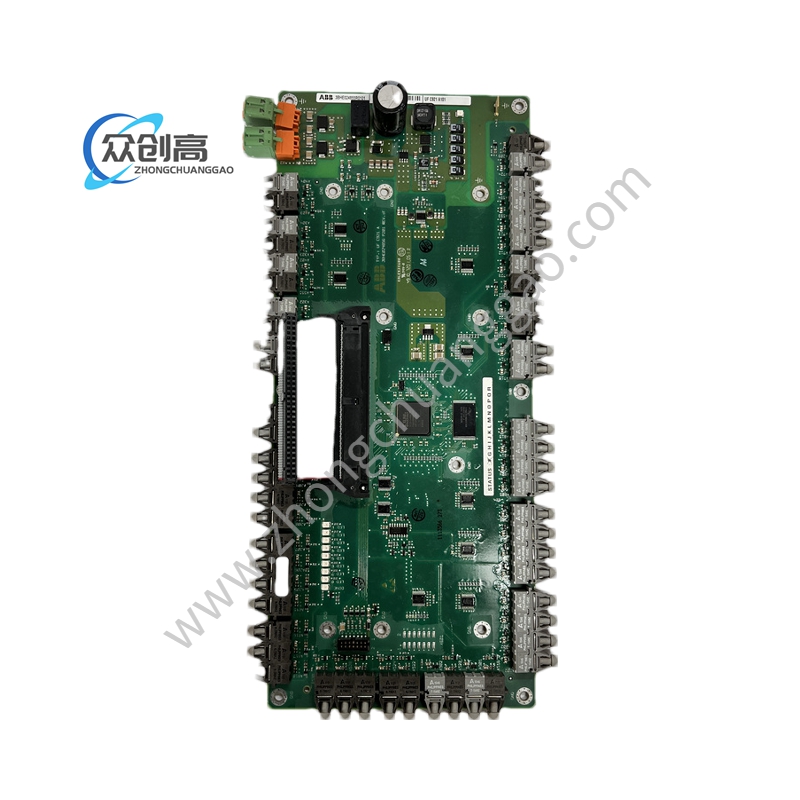
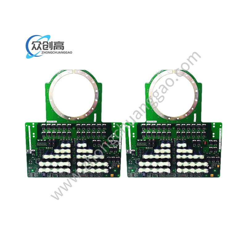
ABB DLM02
降低电枢电压调速,电枢回路必须有可调压的直流电源,电枢回路及励磁回路电阳尽可能小,电压降低转速下降,人为特性硬度不变、运行转速稳定,可无级调速,改变电枢电压主要是从额定电压往下降低电枢电压,从电动机额定转速向下变速,厘恒转矩调速方法。对于要求在一定范围内无级平滑调速的系统来说,这种方法最好。电枢电流变化遇到的时间常数较小,能快速响应,但是需要大容量可调直流电源,
2、电枢回路串电阳调速,人为特性是一族过理想空载点的射线,串电阳越大,机械特性越软、转速越不稳定,低速时串电阳大,损耗能量也越多效率变低,调速范围受负载大小影响,负载大调速范围广,轻载调速范围小,在电动机电权回路外由电阳进行调速的方法,设备简单,操作方便。但是只能有级调速,调速平滑性差,机械特性较软:在调速电阻上消耗大量电能。改变电阻调速缺点很多,目前很少采用。
弱磁调速,一般直流电动机,为避免磁路过饱和只弱磁不能强磁,电枢电压保持额定值,电枢回路串接电阳减至最小,增加励磁回路电阻 Rb励磁电流和磁通减小,电动机转速随即升言,机械特性变软,改变磁通可以以实现无级平滑调速,但只能减弱磁通,从电动机额定转速向上调速量恒功率调速方法。电权电流变化时遇到的时间常数要大很多,响应速度较慢,但所需电源容量小.
注意:转速升高时,如负载转仍为额定值,则电动机功率将超过额定功率,电动机过载运行、这是不允许的,航以弱碰调速时,随着电动机转速的升高,负载转矩相应减小,厘恒功率调速。为避免电动机转子绕组受离心力过大而撤开损坏,弱磁调速时应注意电动机转速不超过允许限度。
3、改变电枢的电刷接入位置
改变电枢绕组与励磁绕组的偏移角来改变直流电机的放置方向
另外,他励和并励直流电动机一般采用电枢反接法来实现正反转。他励和并励直流电动机不宜采用励磁绕组反接法实现正反转的原因是因为励磁绕组西数较多,电感量较大,当励磁绕组反接时,在励磁绕组中便会产生很大的感生电动势,这将会损坏闸刀和励磁绕组的绝缘
To reduce the armature voltage for speed regulation, the armature circuit must have an adjustable DC power supply. The armature circuit and excitation circuit should have as little electric current as possible, and the voltage should be reduced to decrease the speed. The human characteristic hardness should remain unchanged, and the operating speed should be stable. Stepless speed regulation can be achieved. Changing the armature voltage mainly involves reducing the armature voltage from the rated voltage, changing the speed from the rated speed of the motor, and using a constant torque speed regulation method. For systems that require stepless smooth speed regulation within a certain range, this method is the best. The time constant encountered by the armature current change is small and can respond quickly, but requires a large capacity adjustable DC power supply,
2. The artificial characteristic of the armature circuit is a series of rays passing through the ideal no-load point. The larger the series current, the softer the mechanical characteristics and the more unstable the speed. At low speeds, the greater the series current, the more energy is lost, and the efficiency decreases. The speed regulation range is affected by the size of the load. The load is large, and the speed regulation range is wide, while the light load speed regulation range is small. The method of speed regulation by the electric current outside the motor power circuit is simple in equipment and convenient in operation. However, there can only be stepwise speed regulation, with poor smoothness and soft mechanical characteristics: a large amount of electrical energy is consumed in the speed regulation resistor. There are many drawbacks to changing resistance speed regulation, and it is currently rarely adopted.
Weak magnetic speed regulation, generally for DC motors, in order to avoid oversaturation of the magnetic circuit, only weak magnetic cannot be strong magnetic. The armature voltage is maintained at the rated value, and the armature circuit is connected in series to minimize the positive current. Increasing the excitation circuit resistance Rb, the excitation current and magnetic flux decrease, and the motor speed immediately increases. The mechanical characteristics become soft, and changing the magnetic flux can achieve stepless smooth speed regulation. However, it can only weaken the magnetic flux and increase the speed from the rated speed of the motor to a constant power speed regulation method. The time constant encountered when the power current changes is much larger and the response speed is slower, but the required power capacity is small
Attention: When the speed increases, if the load is still at the rated value, the motor power will exceed the rated power, and the motor will run over load. This is not allowed. When adjusting the speed with weak impact, as the motor speed increases, the load torque will correspondingly decrease, and the constant power speed regulation will be applied. To avoid damage to the motor rotor winding due to excessive centrifugal force, attention should be paid to ensuring that the motor speed does not exceed the allowable limit during weak magnetic speed regulation.
3. Change the brush connection position of the armature
Change the offset angle between the armature winding and the excitation winding to change the placement direction of the DC motor
In addition, separately excited and parallel excited DC motors generally use the armature reverse connection method to achieve forward and reverse rotation. The reason why it is not suitable to use the excitation winding reverse connection method to achieve positive and negative rotation for separately excited and parallel excited DC motors is because the excitation winding has a large number of westerns and inductance. When the excitation winding is reverse connected, a large induced electromotive force will be generated in the excitation winding, which will damage the insulation of the switch and excitation winding
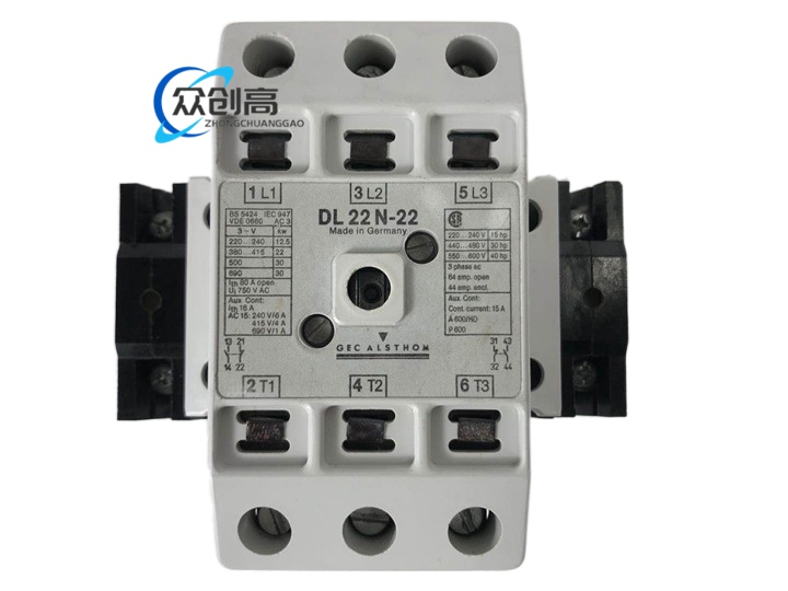 ABB DL21N-22
 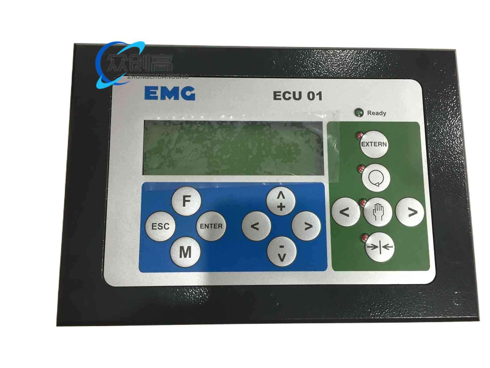 ABB ECU01
 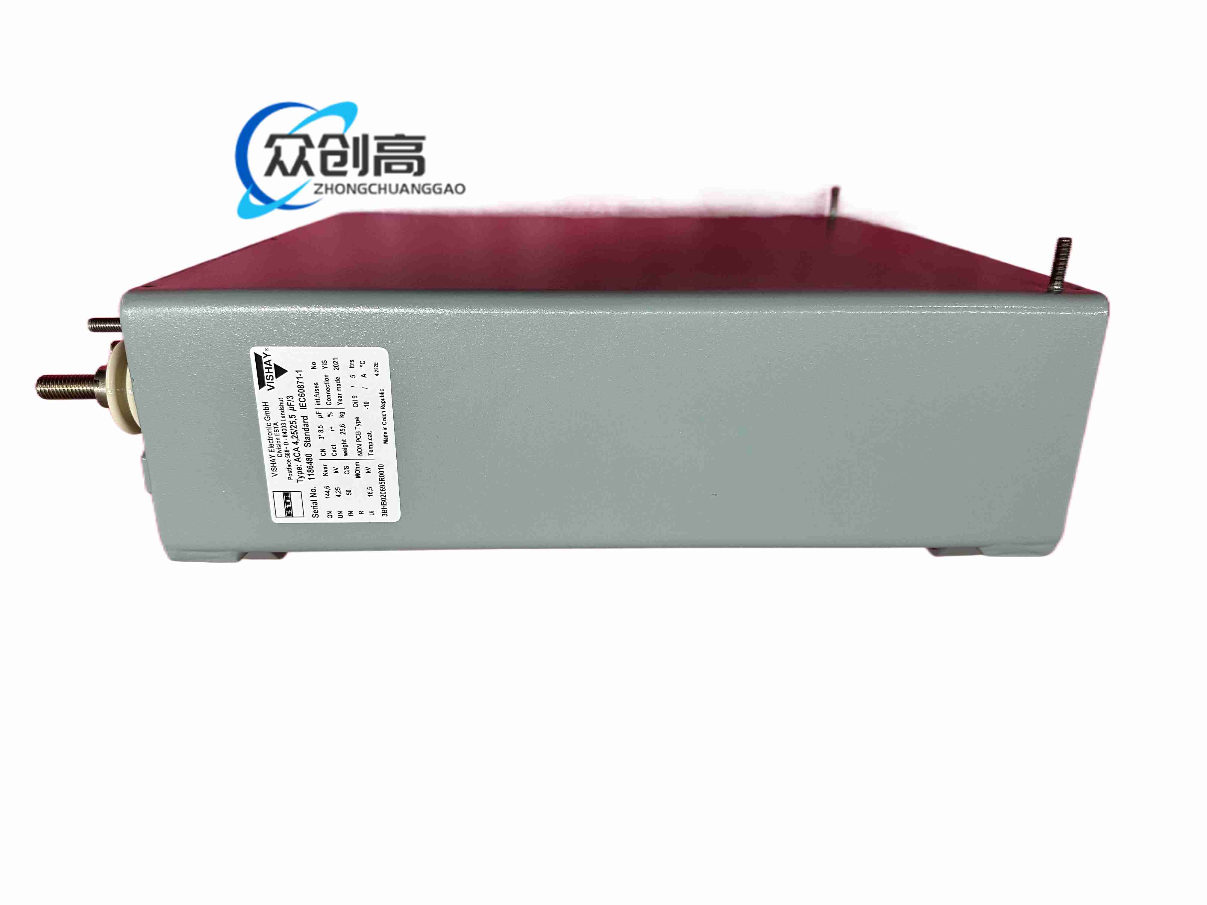 ABB ACA 4,2525,5 ΜF3 3BHB020695R0010
 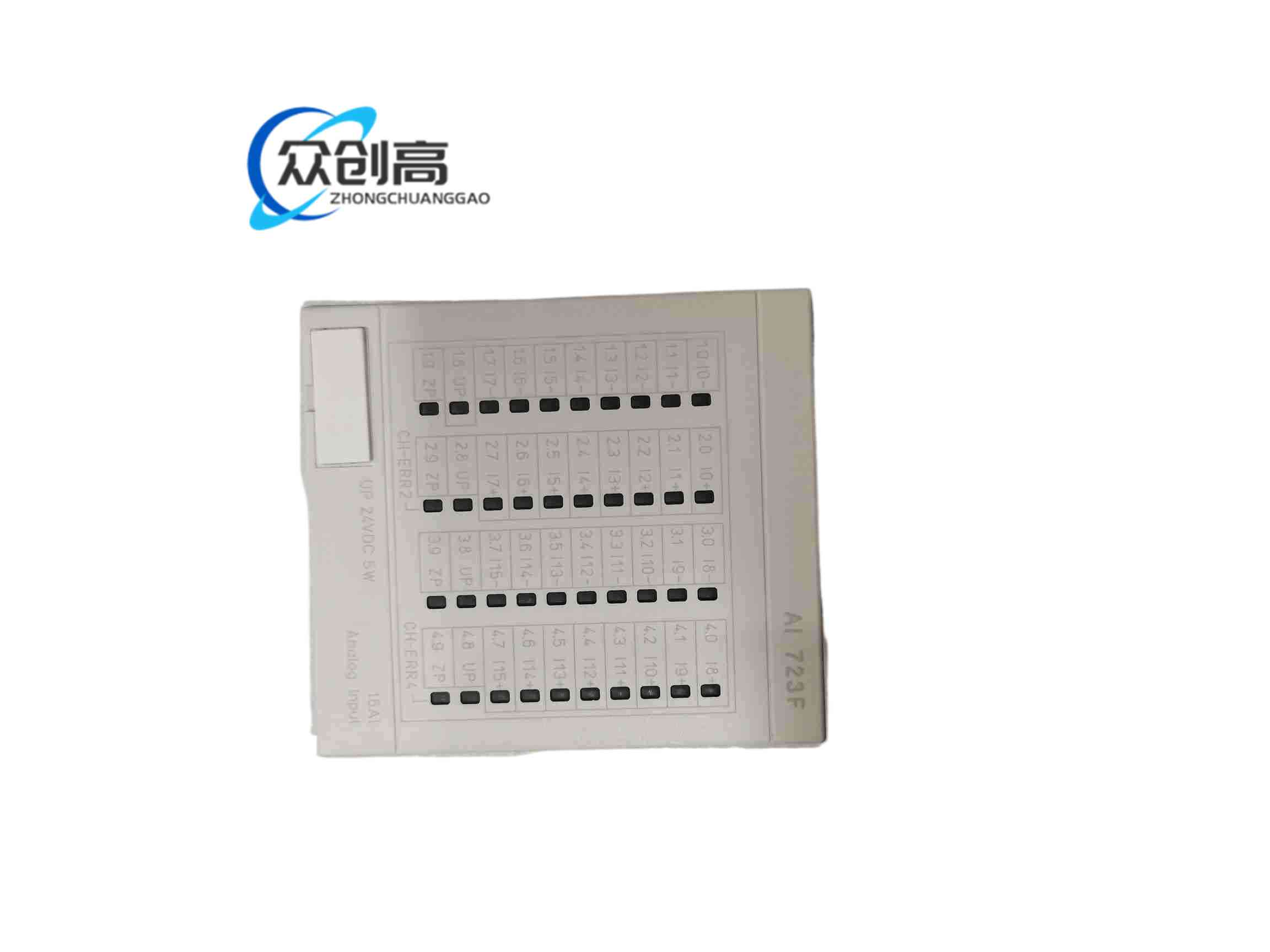 ABB AI 723F